Ceph Deployment
We will not elaborate on the introduction of Ceph in this content.
This project uses 5 machines to form a hyper-converged environment, running some services and using SDN for network management.
I. Hardware Configuration
Due to cost considerations, older model machines are used.
| Type | Model | Quantity |
|---|---|---|
| Server | Huawei FusionServer 2288H v5 | 1 |
| CPU | Intel® Xeon® Gold 6148 Processor 27.5M Cache, 2.40 GHz | 2 |
| Memory | Samsung 32G 2Rx4 PC4-2933Y | 8 |
| Hard Disk | Toshiba HDWT740 S300 Series 5400RPM 128M 3.5 SATA3 | 8 |
| Network Card | Huawei SP333 Dual-port 25G SFP28 PCI-E 8X | 2 |
| Power Supply | Huawei PAC9000S12-BE 900W Power Supply | 2 |
| RAID Controller | Huawei SR430C BC61ESMLB | 1 |
| System Disk | INTEL S3510 120G MLC 200TBW SATA3 SSD | 2 |
| Cache Disk | Samsung 1725B PCIE3.0 X8 1.6T AIC PCIE 8X | 1 |
| Switch 1 | H3C S6520-24S-SI | 1 |
| Switch 2 | H3C S1850v2-28P-HPWR-EI | 1 |
II. Ceph Design
We use HDDs to save costs and U.2 as cache disks.
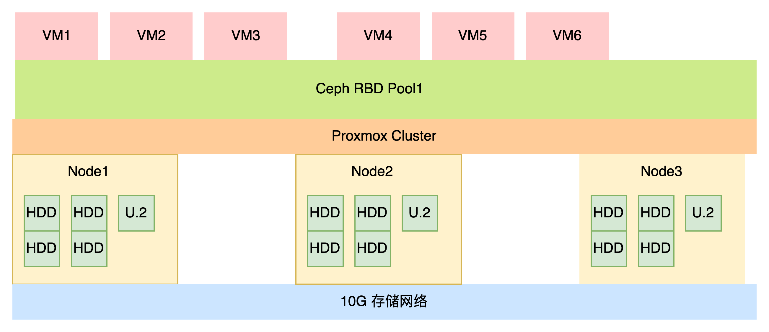
Cache disks significantly improve performance in all-HDD Ceph scenarios. The principle is shown in the following diagram:
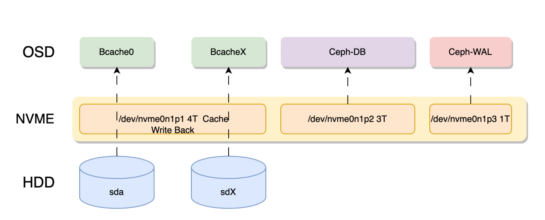
The above diagram shows a 7.68T NVMe drive divided into 3 parts, with a 4T partition used as bcache.
The others are used for storing Ceph OSD's DB and WAL.
Since PVE uses LVM to manage DB and WAL, we don't need to create separate partitions. We can just specify one partition, and PVE will automatically create LVM in this partition to store the Ceph DB.
SSD Cache Selection
SSD Model Selection
Generally, SSD performance has bottlenecks. If you want to use SSD as a cache, it's best to use SAS SSDs.
For NVMe, enterprise-grade NVMe is recommended. M.2 drives should not be used. Using PCIe 4.0 U.2 drives, such as the CD6, is undoubtedly an excellent choice.
Due to cost considerations, we still use the 1.6T 1725b AIC version. The AIC version means it's like a graphics card - a PCIe device that can be inserted into a PCI slot.
SSD Size
According to BlueStore deployment recommendations, the DB storing metadata should be greater than or equal to 4% of the main storage capacity. For 4T, the DB size should be 160G.
However, since we're storing virtual machine data using RBD, the DB size can be 1-2% of the physical disk. For 4T, the DB requirement is 80G. With eight 4T disks, the DB should be 640G. Following official recommendations, our NVMe DB disk would need to be at least 3.2T.
The WAL size usually has no specific requirements. 20-30G is sufficient.
We want the bcache cache to fully manage sequential and random I/O, so the bcache cache size should be large enough. 5-10% per disk is optimal. For example, a 4T disk should have a cache size between 200G and 400G. Eight disks would require more than 1.6T.
Number of SSDs
Single-disk caching poses a risk of disk failure, so consumer-grade SSDs and NVMe drives are not recommended.
Normally, you need to protect against cache disk failure, so multiple disks for caching are recommended.
For example, with eight 4T disks and two SSDs, SSD0 can cache HDD0-HDD3, and SSD1 can cache HDD4-HDD7.
The most secure approach is to use two SAS or SATA drives with hardware RAID 1 for caching. This makes the cache disk less likely to fail. However, this requires a high-performance RAID controller.
If your Ceph cluster is large enough and properly deployed, a single enterprise cache disk can also work. If the cache disk fails, it means the node has failed, but this doesn't affect the overall cluster health as Ceph will auto-repair. Still, using two disks is recommended for better safety.
Reason for Choosing the 1725b
In this project, hot data is relatively limited as we're only running some resident services without desktop requirements. We're using the 1.6T 1725b AIC version.
We allocate 500G for read/write cache, 700G for OSD DB, and 200G for WAL storage. This allocation is relatively reasonable.
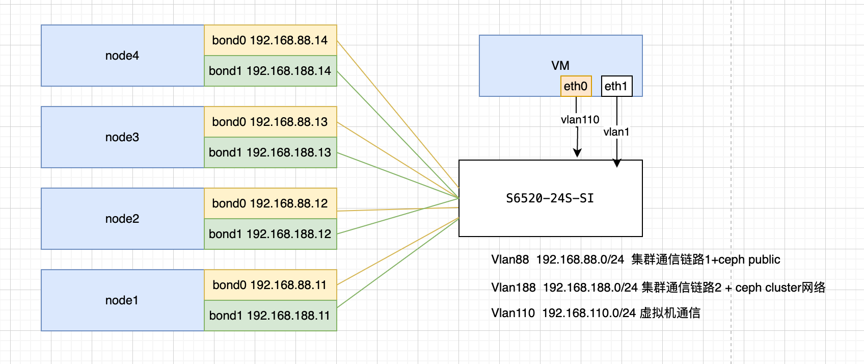
III. Network Architecture
INFO
In best practices, Ceph switches should be set up as primary and backup. In this case, due to project limitations, we're using a single switch.
For example, two S6520 switches could be stacked together, with dual network ports connecting to both switches for stacking.
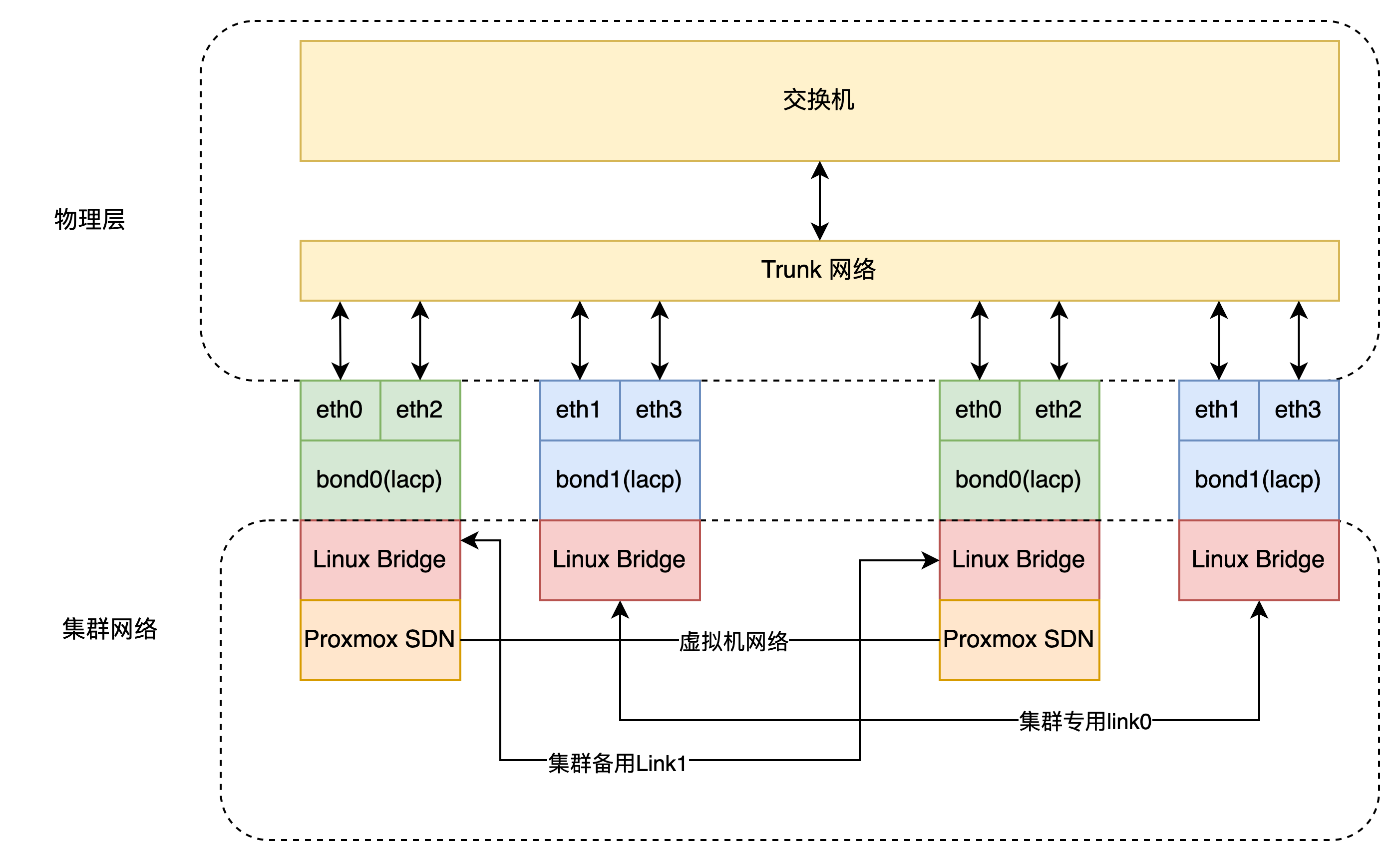
Using PVE SDN functionality, we can set switches to Trunk mode. This allows virtual machine traffic or cluster communication links to be freely configured in PVE without needing to configure the switches. However, for fine-grained control of switch traffic, switch configuration is necessary.
Looking at the logic below, vmbrX and the switch merely act as pure traffic exchange devices. Traffic management on the bridge is controlled through SDN.
Switch Configuration
Below is an example of H3C operations:
Click to view process
First, create an LACP group:
interface Bridge-Aggregation 10Add two network cards to the aggregation group:
interface range xge1/0/21 to xge1/0/22
port link-aggregation group 10 force
Set as dynamic aggregation:
link-aggregation mode dynamic
link-aggregation selected-port minimum 1
link-aggregation selected-port maximum 2
Set trunk:
port link-type trunk
port trunk permit vlan all
PVE Bond
The server comes with two 10G SFP+ network ports, which can be bonded with the PCIe SP333.
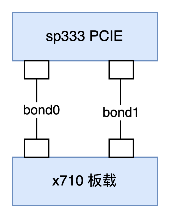
These two bonds are only used for cluster traffic. Below is an example of PVE network configuration:
Click to view PVE network example
auto lo
iface lo inet loopback

iface ens18 inet manual

auto eno1
iface eno1 inet manual

auto eno2
iface eno2 inet manual

iface eno3 inet manual

iface eno4 inet manual

auto ens3f0
iface ens3f0 inet manual

auto ens3f1
iface ens3f1 inet manual

auto bond1
iface bond1 inet manual
        bond-slaves eno2 ens3f0
        bond-miimon 100
        bond-mode 802.3ad
        bond-xmit-hash-policy layer2+3

auto bond0
iface bond0 inet manual
        bond-slaves eno1 ens3f1
        bond-miimon 100
        bond-mode 802.3ad
        bond-xmit-hash-policy layer2+3

auto bond1.188
iface bond1.188 inet static
        address 192.168.188.11/24
# bond1 vlan 188 ceph public network

auto bond0.88
iface bond0.88 inet static
        address 192.168.88.11/24
# bond0 vlan 88 ceph cluster network, handling OSD internal traffic
IV. Installing Ceph
Using the pve-iso-builder project, you can build ISO images with Ceph pre-installed, eliminating the need to install Ceph separately. If your existing system doesn't have Ceph, please refer to the installation method below:
DANGER
Do not install Ceph from the web interface
Installing from the web interface will damage the Ceph software repository.
Click to view process
We recommend installing the latest version, such as ceph-squid.
Add the software repository:
echo "deb https://download.lierfang.com/pxcloud/pxvirt bookworm ceph-squid" > /etc/apt/sources.list.d/pxvirt-ceph.listInstall Ceph on the node:
apt update
apt install ceph -y
If you have many nodes, you can also use the pvessh command for batch operations:
pvessh echo "deb https://download.lierfang.com/pxcloud/pxvirt bookworm ceph-squid" > /etc/apt/sources.list.d/pxvirt-ceph.list
pvessh apt update
pvessh apt install ceph -y
V. Configuring Ceph
Now you can configure Ceph through the web interface.
Make sure to separate the cluster network and public network.
VI. Configuring Bcache Cache
Here we use 500G for bcache, 600G for OSD DB (75G DB per hard disk), and 200G for WAL storage (25G per hard disk).
We use the sgdisk tool for partitioning:
# Clear disk data
dd if=/dev/zero of=/dev/nvme0n1 bs=1M count=16

# Create GPT partition table
sgdisk -ZG /dev/nvme0n1
# Create bcache partition
sgdisk -a1 -n1:1M:+500G  /dev/nvme0n1
# Create DB partition
sgdisk -a1 -n2:501G:+600G  /dev/nvme0n1
# Create WAL partition
sgdisk -a1 -n3:1102G:+200G  /dev/nvme0n1
Create bcache using pvebcache:
pvebcache cache create /dev/nvme0n1p1Create backend disks using pvebcache:
root@node1:~# lsblk
NAME        MAJ:MIN RM   SIZE RO TYPE MOUNTPOINTS
sda           8:0    0   3.6T  0 disk
sdb           8:16   0   3.6T  0 disk
sdc           8:32   0   3.6T  0 disk
sdd           8:48   0   3.6T  0 disk
sde           8:64   0   3.6T  0 disk
sdf           8:80   0   3.6T  0 disk
sdg           8:96   0   3.6T  0 disk
sdh           8:112  0   3.6T  0 disk
sdi           8:128  0 447.1G  0 disk
├─sdi1        8:129  0  1007K  0 part
├─sdi2        8:130  0     1G  0 part
└─sdi3        8:131  0 446.1G  0 part
sdj           8:144  0 447.1G  0 disk
├─sdj1        8:145  0  1007K  0 part
├─sdj2        8:146  0     1G  0 part
└─sdj3        8:147  0 446.1G  0 part
nvme0n1     259:1    0   1.5T  0 disk
├─nvme0n1p1 259:2    0   500G  0 part
├─nvme0n1p2 259:3    0   600G  0 part
└─nvme0n1p3 259:4    0   200G  0 part
We can see that the 3.6T disks are our backend OSD disks that need to be converted to bcache backend devices.
Since they are sequentially numbered, we can use a loop script to process them all:
for id in {a..h} ;do
pvebcache create /dev/sd$id
done
Now we can see bcache on the disks:
root@node1:~# lsblk
NAME        MAJ:MIN RM   SIZE RO TYPE MOUNTPOINTS
sda           8:0    0   3.6T  0 disk
└─bcache0   251:0    0   3.6T  0 disk
sdb           8:16   0   3.6T  0 disk
└─bcache1   251:128  0   3.6T  0 disk
sdc           8:32   0   3.6T  0 disk
└─bcache2   251:256  0   3.6T  0 disk
sdd           8:48   0   3.6T  0 disk
└─bcache3   251:384  0   3.6T  0 disk
sde           8:64   0   3.6T  0 disk
└─bcache4   251:512  0   3.6T  0 disk
sdf           8:80   0   3.6T  0 disk
└─bcache5   251:640  0   3.6T  0 disk
sdg           8:96   0   3.6T  0 disk
└─bcache6   251:768  0   3.6T  0 disk
sdh           8:112  0   3.6T  0 disk
└─bcache7   251:896  0   3.6T  0 disk
sdi           8:128  0 447.1G  0 disk
├─sdi1        8:129  0  1007K  0 part
├─sdi2        8:130  0     1G  0 part
└─sdi3        8:131  0 446.1G  0 part
sdj           8:144  0 447.1G  0 disk
├─sdj1        8:145  0  1007K  0 part
├─sdj2        8:146  0     1G  0 part
└─sdj3        8:147  0 446.1G  0 part
nvme0n1     259:1    0   1.5T  0 disk
├─nvme0n1p1 259:2    0   500G  0 part
├─nvme0n1p2 259:3    0   600G  0 part
└─nvme0n1p3 259:4    0   200G  0 part
Now we add cache to the backend disks:
for id in `seq 0 7` ;do
pvebcache cache attach /dev/bcache$id --cache nvme0n1p1
done
Now we can see the cache information:
root@node1:~# pvebcache list
name       type       backend-dev          cache-dev             state           size            cachemode
bcache0    backend    sdc                  nvme0n1p1            Running         3727GB          writeback
bcache1    backend    sda                  nvme0n1p1            Running         3727GB          writeback
bcache2    backend    sde                  nvme0n1p1            Running         3727GB          writeback
bcache3    backend    sdd                  nvme0n1p1            Running         3727GB          writeback
bcache4    backend    sdg                  nvme0n1p1            Running         3727GB          writeback
bcache5    backend    sdb                  nvme0n1p1            Running         3727GB          writeback
nvme0n1p1  cache      none                 none                 Running         500GB           none
Set cache ratio and sequential cache:
root@node1:~#
for i in `seq 0 7`;do
pvebcache cache set bcache$i --wb-percent 40 --sequential 16384 --cachemode writeback
done
cache_mode: writethrough [writeback] writearound none => writethrough [writeback] writearound none
writeback_percent: 10 => 40
sequential_cutoff: 4.0M => 16.0M
The above command sets the cache ratio to 40% and caches sequential I/O below 16M.
VII. Adding Ceph OSD
We can add OSD through the web interface:
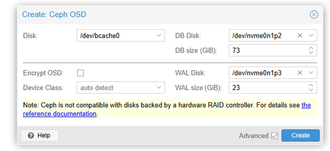
Select bcache for the disk and our disk partition for the DB disk. Note that DB SIZE needs to be specified. We have 600G space for DB and 8 hard disks, so about 75G per disk. Here we set it to 73G.
For WAL Disk, select the WAL partition and specify a size of 23G.
Wait patiently for the creation to complete.
We can also create quickly through the command line:
for disk in `seq 1 7`;do
pveceph osd create /dev/bcache$disk --db_dev /dev/nvme0n1p2 --db_dev_size 73 --wal_dev /dev/nvme0n1p3 --wal_dev_size 23
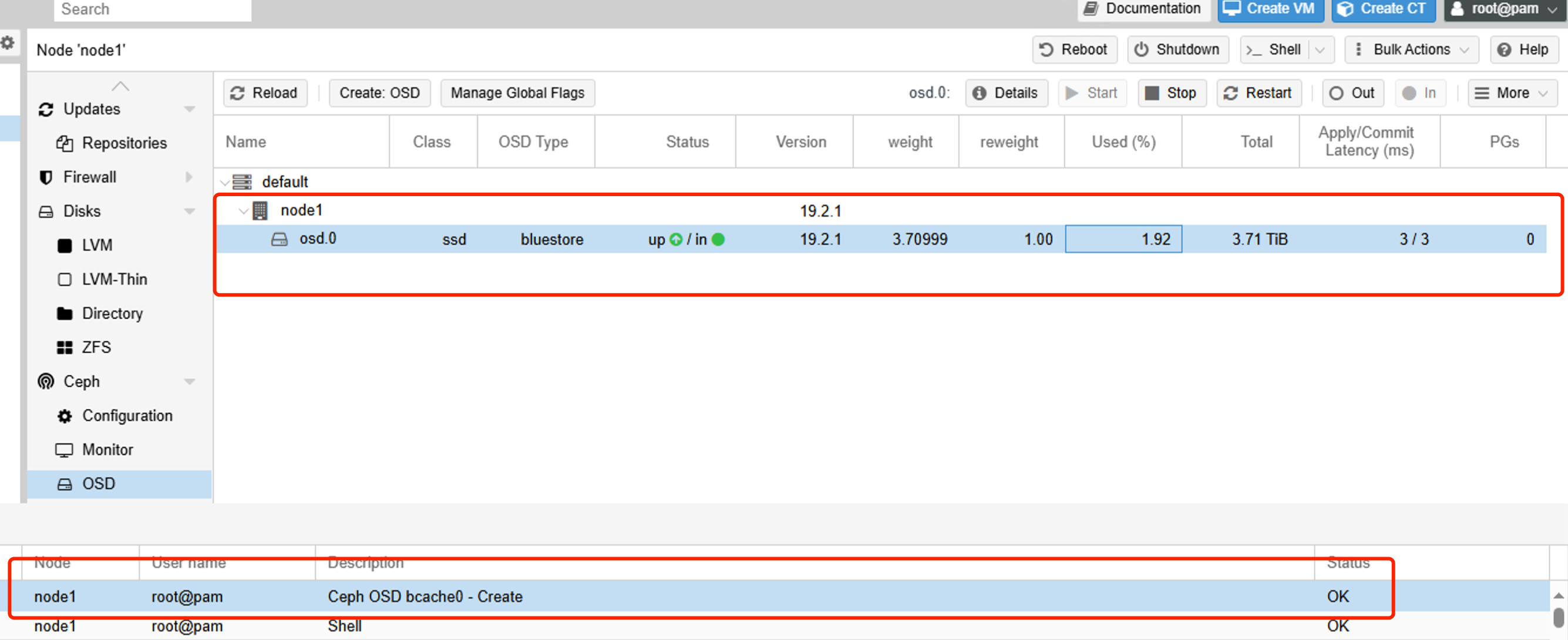
doneThis completes the Ceph setup for one node: 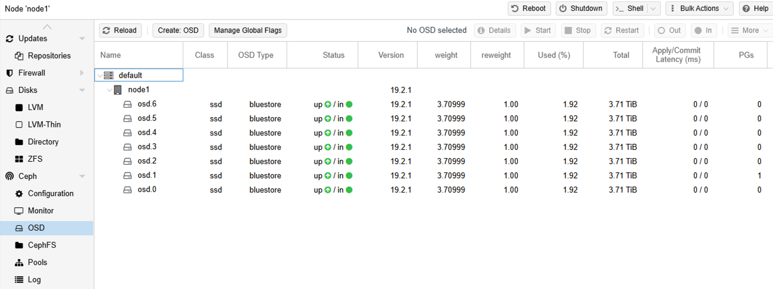
Now we repeat the above steps on the other nodes.
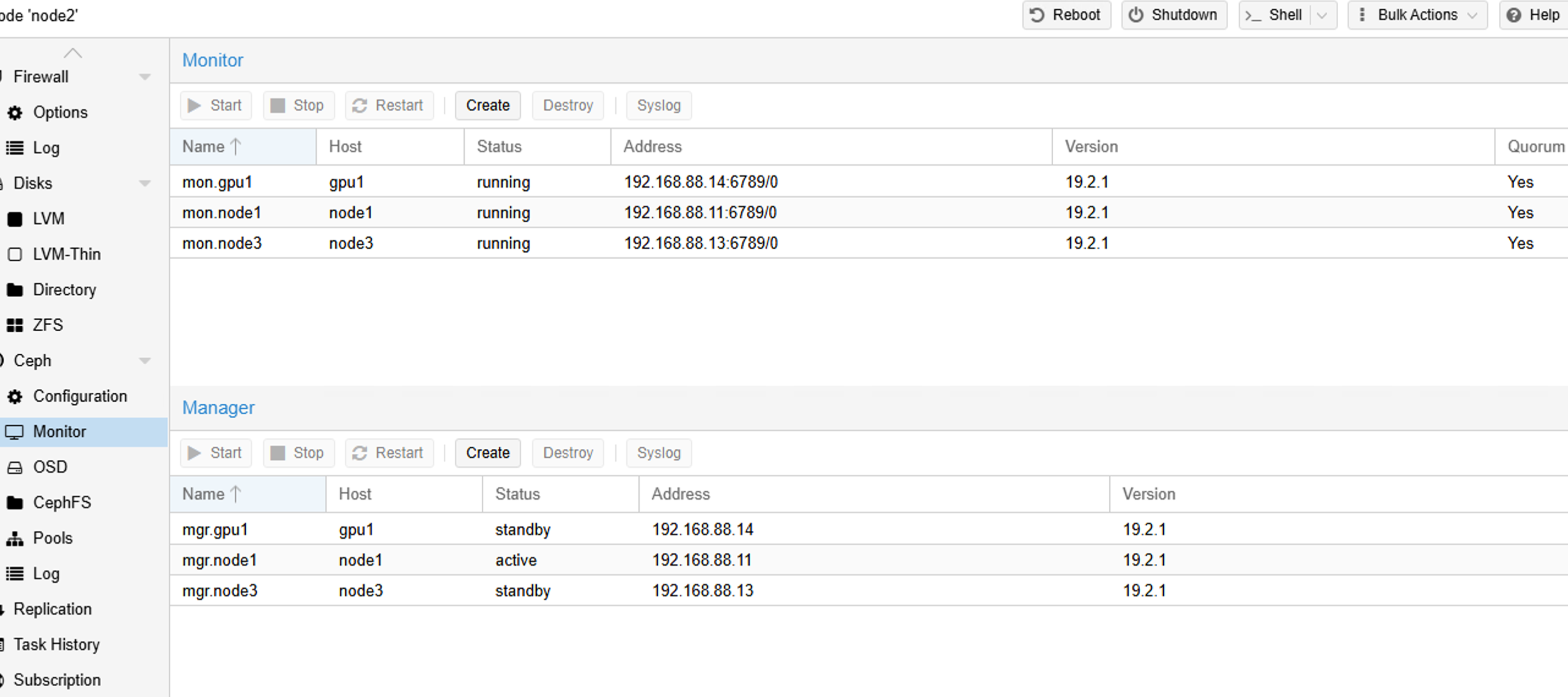
VIII. Adding Ceph Manager and Monitor Nodes
On the PVE web interface, add at least a majority of nodes to ensure stable service operation.
IX. Creating a Ceph Pool for Storing Virtual Machine Disks
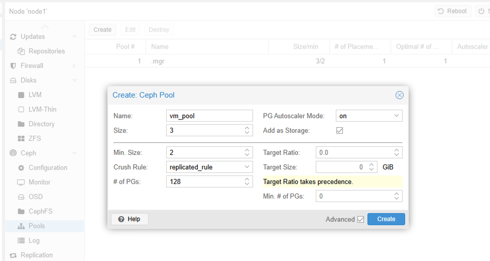
You just need to give it a name. The default is a 3-replica strategy with a minimum of 2 replicas, meaning that if a node or OSD goes offline and the number of replicas falls below 2, the cluster will be frozen.
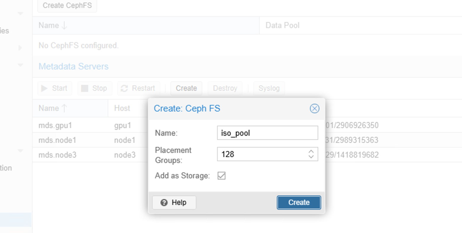
X. Creating a CephFS File Pool
CephFS is a file-type storage that can store ISO images:
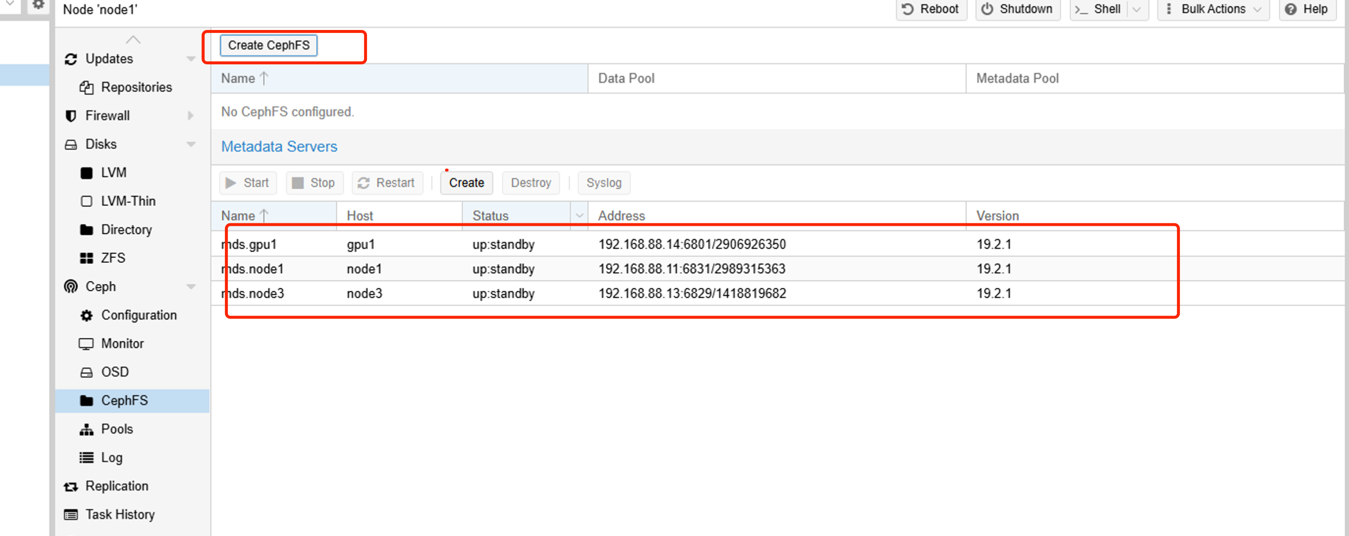
Create a majority of MDS servers, then create a CephFS-type pool:
XI. Configuring NTP Server
Create a virtual machine, install chrony, and configure the NTP service:
apt update && apt install chrony -y
echo "server ntp.aliyun.com iburst" >> /etc/chrony/conf.d/ntpserver.conf  # Use Alibaba Cloud as the upstream NTP time server
echo "allow 192.168.100.0/24" >> /etc/chrony/conf.d/ntpserver.conf # Allow a specific network segment to access
echo "local stratum 10" >> /etc/chrony/conf.d/ntpserver.conf # Allow local timekeeping
systemctl restart chrony
Once the NTP server is configured, add the NTP server address to the cluster:
pvessh echo 'server 192.168.122.253 iburst' > /etc/chrony/sources.d/local-ntp-server.sources
pvessh systemctl restart chrony
Then we can verify:
pvessh chronyc sources -vAfter configuration, we can clone this virtual machine and modify its IP, giving the cluster two NTP time servers for greater stability.